Dolphin Cutter Error 56 Solved
Method for detecting abnormal conductivity of dolphin xp005 probe and milling cutter
Problem:Dolphin key cutting machine error 56 problem:
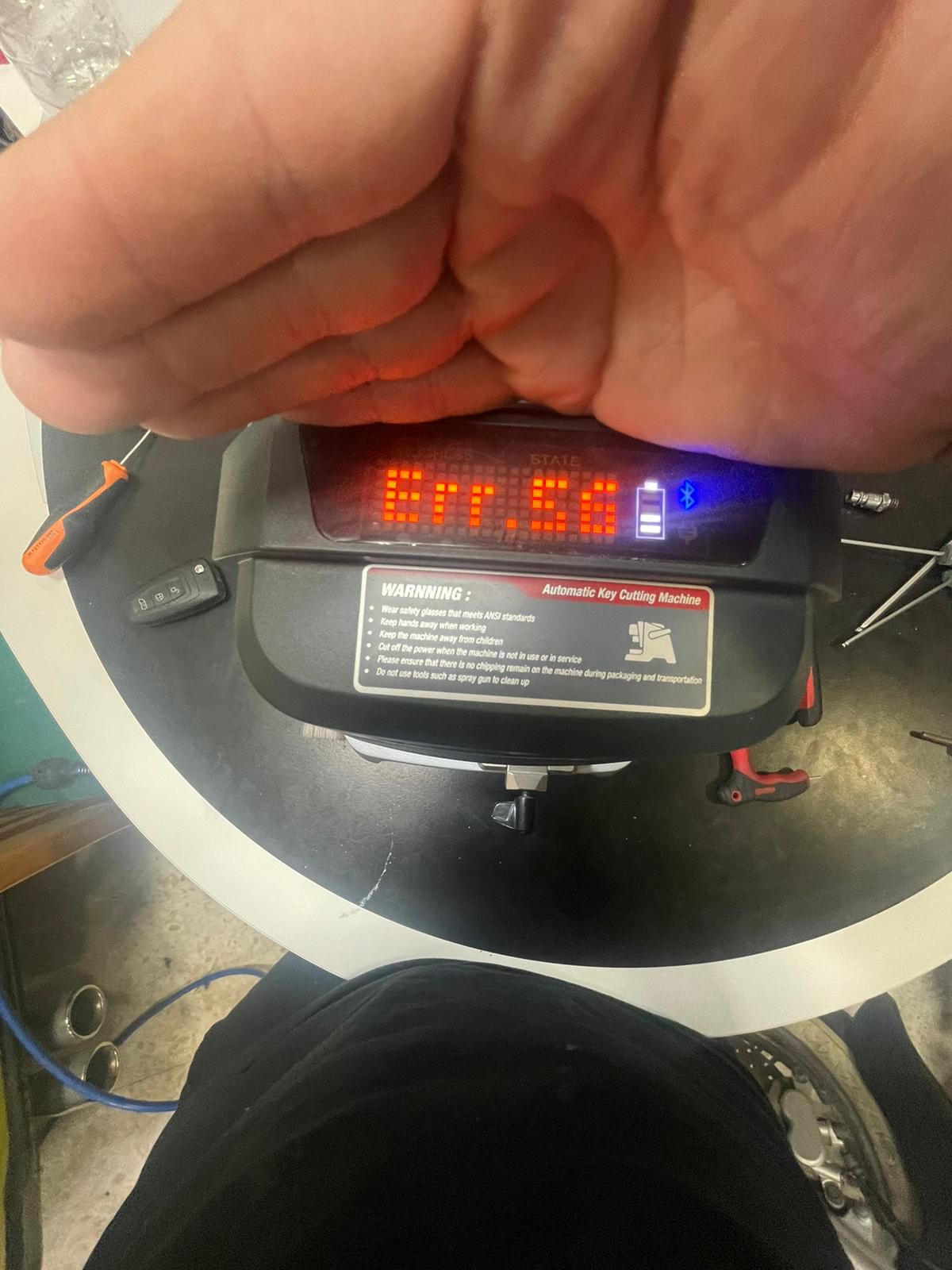
possible reason:
check the conductivity of the milling cutter and try again
solution:
Method for detecting abnormal conductivity of dolphin xp005 probe and milling cutter
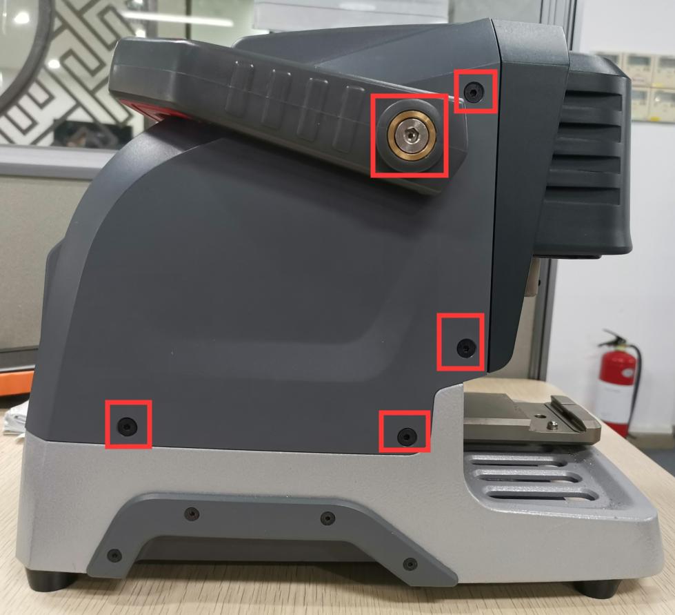
Step1:Disassemble the back cover, and be careful of the wiring harness of the cover when disassembling
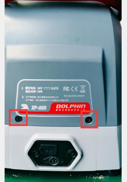
Step2:Remove the back cover, you can see these things, take off the wire harness, and remove the Phillips screws (see Figure 1). Take out the rubber pellets from the front of the device. There are screws inside. This strip needs to be removed (Figure 2)
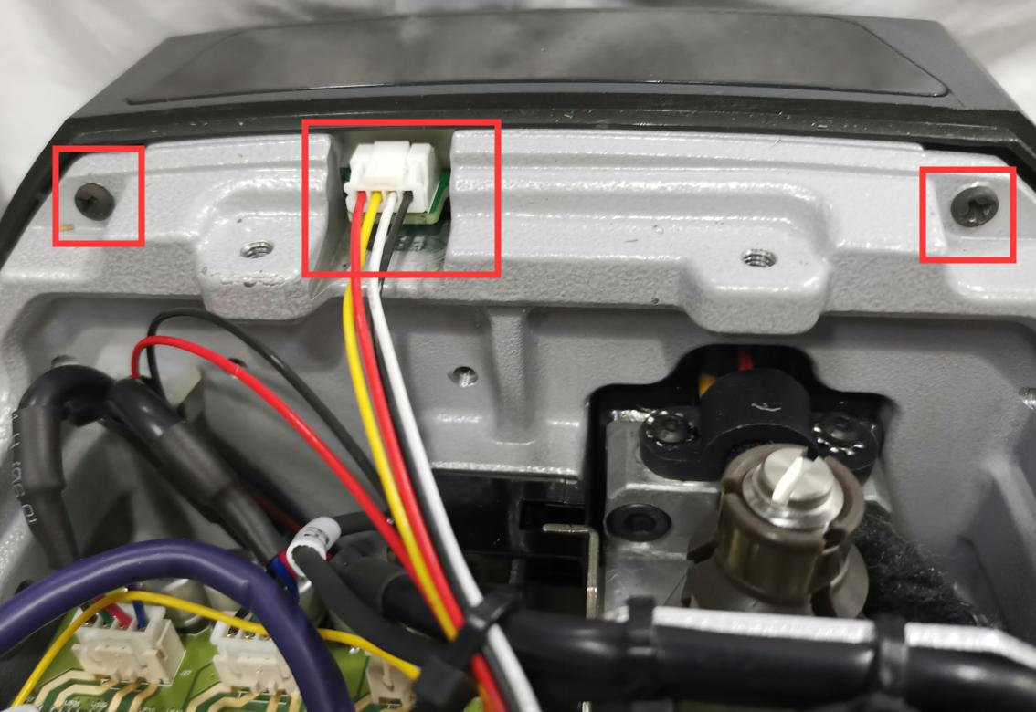
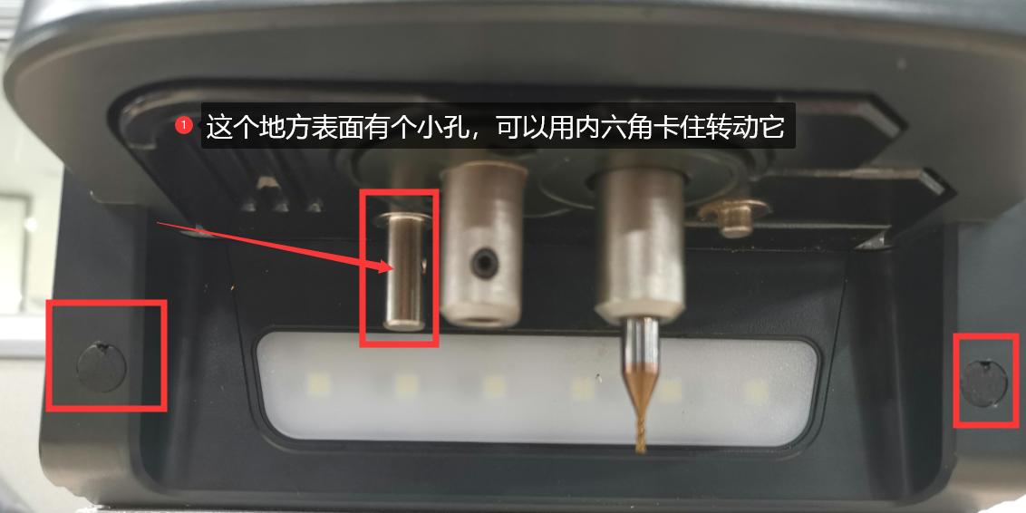
(Figure 1) (Figure 2)
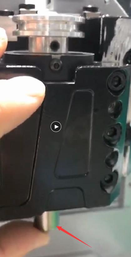
Step3:Use a flat-blade screwdriver to turn the lead screw, align the Z-axis and the outer cover on a horizontal surface (as shown in Figure 3 and Figure 4), remove the Z-axis housing after alignment (as shown in Figure 5), and place the probe next to it. Remove the screws (as shown in Figure 6). Remember to be careful when removing it. There is a conductive wire inside (as shown in Figure 7).
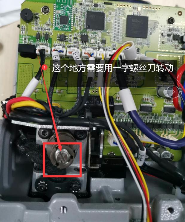
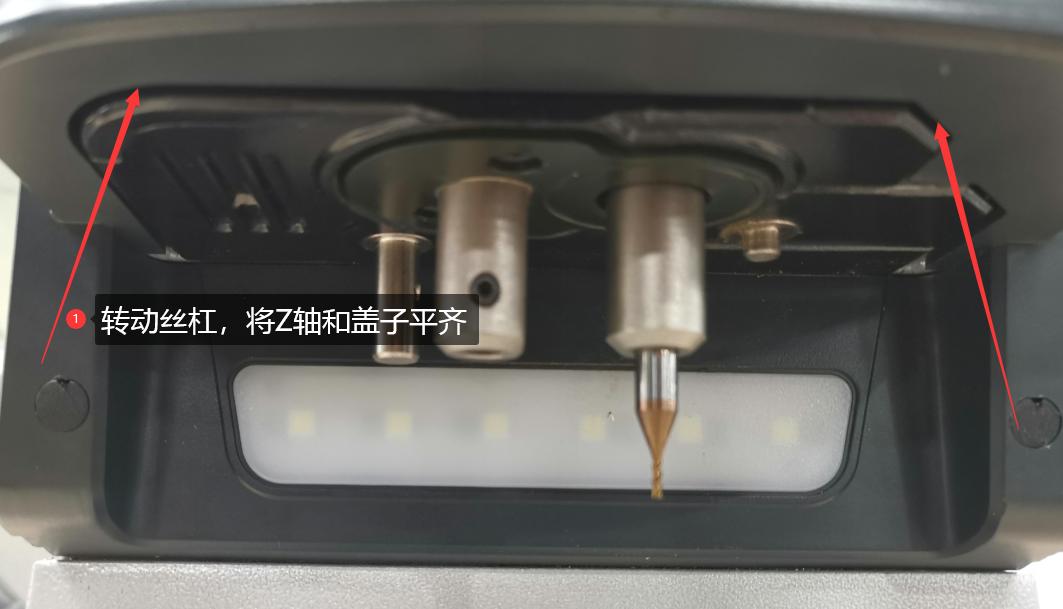
(Figure 3) (Figure 4)
(Figure 5) (Figure 6)
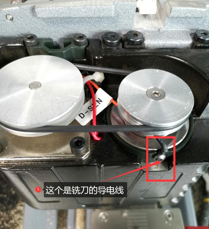
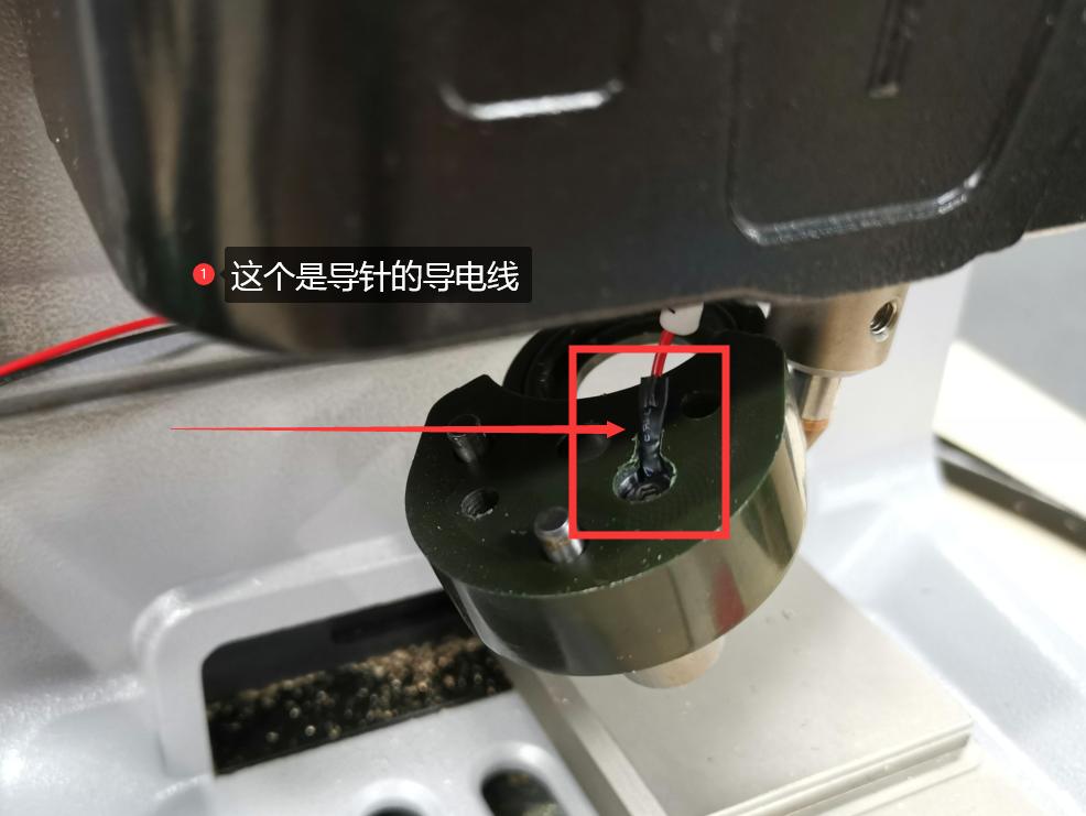 (Figure 7)
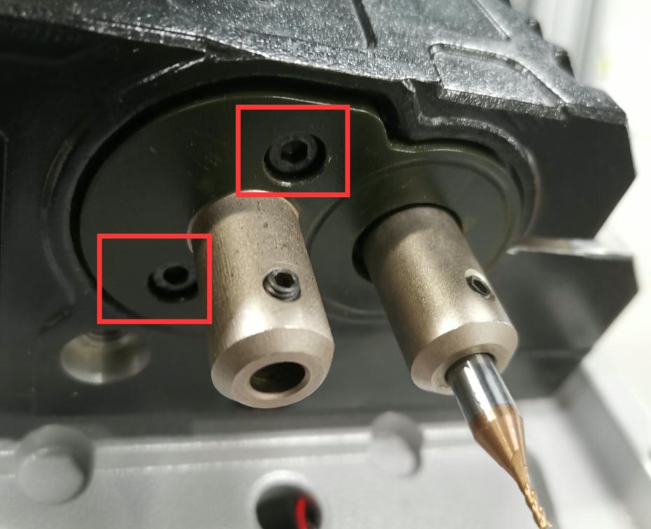
Step4:If the above steps are all done, the next step is to check whether the conductive wires of the milling cutter and the probe are conductive or short (as shown in Figure 5 and Figure 7), which needs to be combined with the main board to detect. (Figure 8) (or plug in the cable on the main board, and then check whether the conductivity is normal)
 (Figure 8)
Step5(conductivity of cutter):Loosen the 3 screws of the Z axis (as shown in Figure 9), and then tighten the two screws (as shown in Figure 10). Push these two screws to the inside until there is a gap. This is to take out the shaft (as shown in Figure 11), press your finger on the position of the milling cutter hole, and push it up with a little force. Come up, and then observe whether the white paper inside is broken (as shown in Figure 12), if it is broken, it needs to be replaced. If it is not broken, observe whether there is iron filings in the bearing hole
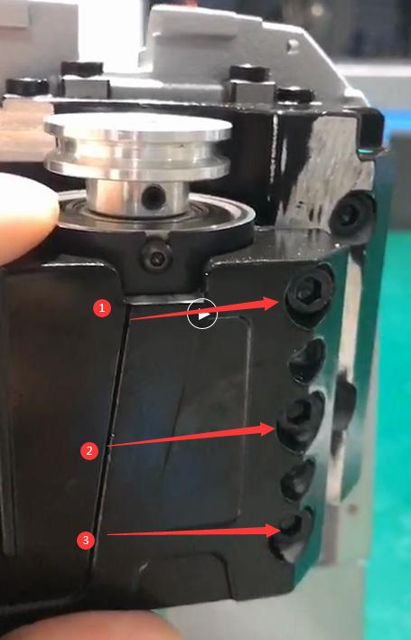
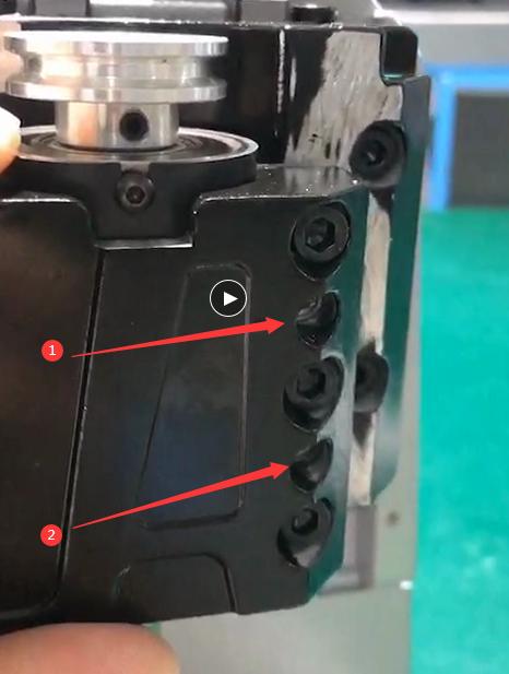
(Figure 9) (Figure 10)
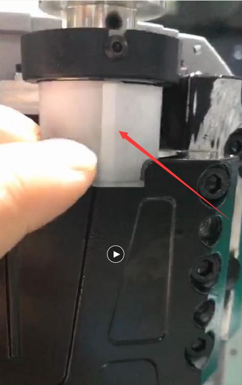
(Figure 11) (Figure 12)